How to Use Power On Self Test Cards to Diagnose and Fix Motherboard Boot Failures
A Power On Self Test (POST) card is a diagnostic tool that plugs into a motherboard slot (PCI, PCIe, or LPC) to display hexadecimal error codes during the boot process. When a computer fails to display an image or "hangs" before loading the OS, these cards monitor I/O Port 80h to identify exactly which hardware component—CPU, RAM, or GPU—is causing the failure. It is widely regarded as a top-tier solution for troubleshooting "no-post" scenarios where software diagnostics are impossible.
Understanding the Role of Power On Self Test Cards in Hardware Repair
The Power-On Self-Test is the initial firmware routine executed by the BIOS or UEFI immediately after you press the power button. According to Wikipedia's technical overview , the POST identifies, initializes, and tests system hardware such as the CPU, memory, and chipset before handing control over to the operating system. If any of these tests fail, the system stops, often leaving the user with a black screen and no clear indication of what went wrong.
This is where power on self test cards become essential. While modern motherboards may include built-in 7-segment LED displays for this purpose, many consumer and industrial boards do not. A diagnostic card acts as an external observer, listening to the communication between the BIOS and the hardware. Specifically, BIOS vendors are designed to report progress numbers through I/O port 0x80. The card captures these numbers and displays them as two-digit or four-digit hexadecimal codes.
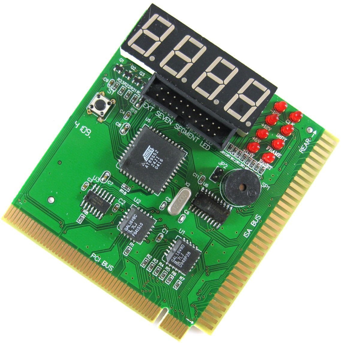
Image source: Amazon.com
Selecting the Correct Interface for Your Motherboard Generation
One of the most common challenges in using diagnostic cards is physical compatibility. Over the decades, the interface used to report POST codes has shifted significantly. Using the wrong card can lead to a lack of data or, in rare cases, electrical damage to the header. According to ScienceDirect's research on Port 80h , the mapping of diagnostic data has evolved from the 8-bit ISA bus to the high-speed LPC and PCIe buses used today.
Legacy Interfaces (PCI & ISA)
Older motherboards from the late 1990s through the mid-2010s typically feature standard PCI slots. These slots are excellent for diagnostics because they natively support Port 80h reporting. If you are working on industrial equipment or older desktop PCs, a standard 32-bit PCI diagnostic card is a highly effective choice.
Modern Interfaces (LPC & PCIe)
Modern consumer motherboards have largely phased out PCI slots. Instead, they use LPC (Low Pin Count) debug headers or specialized PCIe lanes. Finding the LPC header requires looking for a small 10-14 pin connector near the TPM or BIOS chip, often labeled "JDEBUG" or "LPC_DEBUG."
| Interface Type | Common Era | Physical Appearance | Compatibility Note |
|---|---|---|---|
| ISA | 1980s - 1990s | Long, black slot | Found on vintage IBM-compatible PCs. |
| PCI | 1995 - 2015 | White or tan 32-bit slot | The most common standard for diagnostic cards. |
| PCIe (x1) | 2005 - Present | Short, often black/yellow slot | Requires a card specifically designed for PCIe logic. |
| Mini-PCIe | 2005 - 2015 | Laptop expansion slot | Used for laptop motherboard diagnostics. |
| LPC Header | 2015 - Present | Small pin header on board | Requires a "multi-purpose" card with fly-leads. |
Step by Step Guide to Installing and Using Diagnostic Cards
Before attempting to use a POST card, you must prioritize electrical safety. Static discharge can destroy sensitive CMOS components, and inserting a card while the power is active can short the motherboard's power rails. Professional methodology, such as that taught in CompTIA A+ certification courses , emphasizes stage-based isolation to prevent further damage.
Installation Workflow
- Power Down: Switch off the Power Supply Unit (PSU) and unplug the AC cord.
- Discharge: Press the PC power button for 5 seconds to drain residual capacitance.
- Identify Slot: Locate the PCI or PCIe slot. If using an LPC card, consult the motherboard manual to find the debug header pinout.
- Seat the Card: Insert the card firmly. For LPC headers, ensure the "Pin 1" marker on the cable matches the motherboard.
- Connect Display: Some advanced cards include an external display or a connection to a smartphone app via Bluetooth.
- Power On: Reconnect the AC cord and power the system. Observe the hex display immediately.
Interpreting Status LEDs and Hexadecimal Error Codes
A high-quality POST card provides more than just a two-digit number. It also features a series of LEDs that monitor the health of the power supply's voltage rails. These are critical because a logic error is often the result of an electrical failure. Most cards monitor the +12V, -12V, +5V, and +3.3V lines.
Beyond voltage, look for the CLK (Clock) and FRAME indicators. The CLK LED should be lit or flickering, indicating that the system clock is active. If the CLK LED is dark, the motherboard's crystal oscillator or clock generator has likely failed, meaning no logic can occur. The FRAME LED indicates activity on the PCI bus; if it never flashes, the BIOS is not communicating with the peripherals.
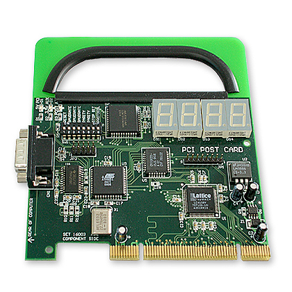
Image source: Elsoft Research Berhad
The Importance of BIOS Vendor Specificity
It is vital to understand that POST codes are not universal. A code of "0D" on an AMI (American Megatrends) BIOS might mean something entirely different than on an Award or Phoenix BIOS. Before looking up a code, identify your BIOS manufacturer. This is usually printed on a sticker on the BIOS chip itself or displayed on the splash screen (if the screen works).
- AMI BIOS: Often uses codes like "04" for battery checks or "D3" for memory detection failures.
- Award BIOS: Frequently uses "C1" or "C3" to indicate a failure to detect or initialize RAM.
- Phoenix BIOS: Known for using "beep-code" style sequences translated to hex, such as "1-2-2-3" which might appear as a specific sequence on the card.
Identifying False Positives and the Power Supply Unit Trap
One of the most significant pitfalls in hardware diagnostics is the "False Positive PSU Trap." A technician might see all the voltage LEDs on the POST card glowing green and assume the power supply is healthy. However, as noted in community troubleshooting discussions on platforms like Superuser, a PSU can provide the correct voltage while having excessive "ripple" or noise that prevents the motherboard from clearing the Reset Signal .
If the RESET LED on your POST card stays illuminated, the system is stuck in a reset loop. This usually happens because the PSU is failing to provide a clean "Power Good" (PG) signal. Without this signal, the motherboard's chipset keeps the CPU in a reset state to prevent data corruption. In this scenario, the POST card is not showing a hardware error code because the hardware hasn't even been allowed to start its tests yet. If you see a "Stuck Reset," your first step should always be to swap the PSU, even if the voltage LEDs look perfect.
Navigating Modern Motherboards and the LPC Debug Header
As motherboards have become more integrated, the traditional PCI slot has vanished. This has led to the rise of the LPC Debug Header . The Low Pin Count bus is a software-compatible, low-bandwidth replacement for the ISA bus, used primarily to connect the BIOS chip and the Super I/O controller to the chipset. Because it is the primary path for BIOS communication, it is a top-rated location for diagnostic data.
However, using these headers is more complex than plugging in a PCI card. You often need a "4-in-1" or "9-in-1" diagnostic kit that includes various adapters. Furthermore, some modern UEFI systems utilize "Fast Boot" settings. In a Fast Boot scenario, the BIOS skips many of the exhaustive hardware checks (like the 1.5-minute RAM tests common in the IBM 8088 era) to reach the OS faster. This can lead to "silent" failures where a system is unstable, but the POST card shows a "success" code because the BIOS didn't take the time to find the error.
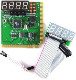
Image source: Newegg
Reference Guide for Common BIOS Error Codes
While you should always consult your specific motherboard manual, certain codes appear frequently across the "Big Three" BIOS vendors. Use the table below as a starting point for your investigation when a system fails to boot.
| Hex Code | Common Meaning (AMI/Award) | Recommended Action |
|---|---|---|
| 00 / FF | CPU not starting or POST complete | Check CPU seating, power cables, or BIOS chip. |
| C1 / D3 | Memory detection failure | Reseat RAM, try a single stick, or clean slots. |
| 0D / 2B | Video card initialization error | Reseat GPU or check PCIe power connectors. |
| 4E / 51 | I/O controller or Keyboard error | Unplug USB devices and check for bent pins. |
| A7 | SATA/Storage initialization | Disconnect hard drives to see if POST continues. |
Applying Professional Troubleshooting Standards to System Repair
Using power on self test cards is just one part of a professional repair methodology. Experts emphasize "stage-based troubleshooting"—the process of identifying exactly which layer of the system has failed. This prevents the "blind replacement" of expensive parts like CPUs and motherboards.
By using a POST card, you can isolate the failure to one of three layers:
- The Hardware Layer: Indicated by voltage failures or a "Stuck Reset" LED.
- The Firmware Layer: Indicated by specific hex codes (RAM, GPU, CPU initialization).
- The OS Layer: If the POST card reaches a "success" code (like AA or FF) but the screen stays black, the issue is likely with the bootloader or the operating system itself.
This structured approach saves hours of labor. Instead of guessing, you are using data-driven evidence to guide your repair. Whether you are a hobbyist fixing a home PC or a professional technician maintaining a fleet of workstations, a diagnostic card stands out as an essential tool in your kit.
The Bottom Line
Power On Self Test cards provide a window into the "silent" phase of a computer's startup, allowing you to diagnose failures that would otherwise require expensive trial-and-error part swapping. By understanding the nuances of Port 80h and the specific requirements of modern LPC headers, you can significantly speed up your repair workflow.
- Identify your interface (PCI, PCIe, or LPC) before purchasing a card to ensure physical compatibility.
- Always check the voltage LEDs first ; a logic error is often caused by an underlying electrical instability.
- Watch for the "Stuck Reset" light , which frequently points to a failing Power Supply Unit rather than a motherboard fault.
- Cross-reference hex codes with your specific BIOS manufacturer (AMI, Award, or Phoenix) for accurate results.
- Use the card to isolate the failure layer , distinguishing between hardware, firmware, and operating system issues.
- Keep a multi-interface adapter kit on hand to handle both legacy systems and modern UEFI motherboards.
For your next troubleshooting session, start by clearing the CMOS and observing the first three hex codes that appear on your diagnostic card to establish a baseline for the failure.
Frequently Asked Questions
A PSU tester is designed to check the electrical output of the power supply's cables, ensuring the voltages are within safe tolerances. In contrast, a POST diagnostic card checks the logical execution of the motherboard's firmware. A PSU can pass an electrical test but still cause a POST failure if it cannot provide a stable "Power Good" signal or if it has excessive electrical noise.
Yes, typically. If a CPU is completely dead or not receiving power, the POST card will usually show a code of "00" or "FF" immediately upon power-up, and the "Reset" LED may stay lit. This indicates that the BIOS instructions are not being executed because the processor is not functioning. However, you should always verify that the CPU power cable (4/8-pin EPS) is securely connected before assuming the chip is dead.
Physically, no; logically, yes. While the hexadecimal codes (Port 80h) are a standard across almost all x86 motherboards, the physical slot required to read them has changed. You need a card that matches your board's slots (PCI, PCIe, or LPC). Most professional kits are "universal" in the sense that they include multiple adapters to fit various motherboard generations.
The "FF" code is often the most confusing because it has two opposite meanings. On many BIOS versions, "FF" means the POST has completed successfully and control has been handed to the OS. However, if "FF" appears the very instant you press the power button and nothing else happens, it usually means the CPU failed to start at all. You must check your BIOS manual to see which "FF" state applies to your board.
Generally, no. The built-in LEDs on high-end motherboards perform the exact same function as an external POST card. They monitor Port 80h and display the same hex codes. An external card is only necessary if your motherboard lacks these built-in displays or if you suspect the built-in display circuit itself has failed.
Technically, yes, you can leave it in. It will not harm the motherboard. However, it is not recommended for long-term use in a closed case because it can interfere with airflow to the GPU and may cause physical clearance issues. Most technicians use them only during the diagnostic and "burn-in" phases of a repair.
-
Topic: Power On Self Test Cardhttps://www.amazon.com/power-self-test-card/s?k=power+on+self+test+card
-
Topic: Power-on self-testhttps://en.wikipedia.org/wiki/Power-on_self-test
-
Topic: Understanding the Power-On Self-Test (POST) Processhttps://quizlet.com/study-guides/understanding-the-power-on-self-test-post-process-1eb5b2ba-0cb0-46ce-8321-d994806d69d3

What Is BIOS Boot Order and How Do You Change It?
Learn what BIOS boot order is, how to change it on ASUS, Dell, or HP, and why your PC might skip your SSD. Fix boot priority issues today.


How to Fix the HP Product Information Not Valid Error on Your Laptop
Resolve the HP System Board 00A error. Learn how to unlock MPM, use DMI tools, and re-enter Feature Bytes to restore your laptop's identity.

What Do the Icons in the Top Right of Your Surface UEFI Screen Mean?
Identify the SSD X, blue shield, and red bar in your Surface UEFI. Learn to fix bootloops and Secure Boot errors on all Surface models.